Interactive Hydraulic Calculations
REVIT IN THE DRIVER'S SEAT. KLEPON V8 UNDER THE HOOD.
A model-driven hydraulic calculation engine built directly into the Revit workflow.
Calculation & Analysis Capabilities
Powerful hydraulic calculation, built for real-world fire protection design.
- Revit Model–Driven Hydraulic Calculation
- Supply and Demand Calculation Modes
- Tree and Looped Network Solving
- Hazen-Williams and Darcy-Weisbach Pipe Friction Methods
- Network-Wide Pressure-Loss Analysis
- Equivalent-Length / Fitting / Valve-Loss Handling
- Velocity Pressure (Pv) Calculation
- Antifreeze System Support
- Automatic Open Connection Detection
- Automatic Critical Area Detection
- Automatic Hydraulic Path Analysis
- Node-by-Node Analysis
- Pipe-by-Pipe Analysis
- Available vs. Required Pressure & Safety Margin
- Interactive Model Inspection
- Fast Recalculation
Calculation Settings & Model Configuration
Flexible settings to match your project and workflow.
- Water Supply / Source Definition
- Metric and Imperial Unit Settings
- Easy C-Factor Configuration
- Preset Pressure Reduction
- Fluid Density & Viscosity Settings
- KLEPON Hydraulic Properties Panel
Results, Visualization & Output
Clear results, ready for design review and project delivery.
- Calculation Dashboard
- Automatic Hydraulic Drawing & Visual Analysis
- Automated HC Result Tagging in Drawings
- Automated Source Data Tagging in Drawings
- Detailed Hydraulic PDF Reports
From Revit Model to Hydraulic Network
The hydraulic calculation starts with the system you are already designing in Revit.
KLEPON reads the connected pipe network and turns the relevant model information into a calculation-ready hydraulic network. Pipes, fittings, demand points, elevations, sizes, and other hydraulic properties remain linked to the elements engineers are already working with in Revit.
This removes one of the most repetitive parts of traditional hydraulic calculations: recreating the design in another application before you can calculate it.
The result is one connected workflow built on the same source of information.
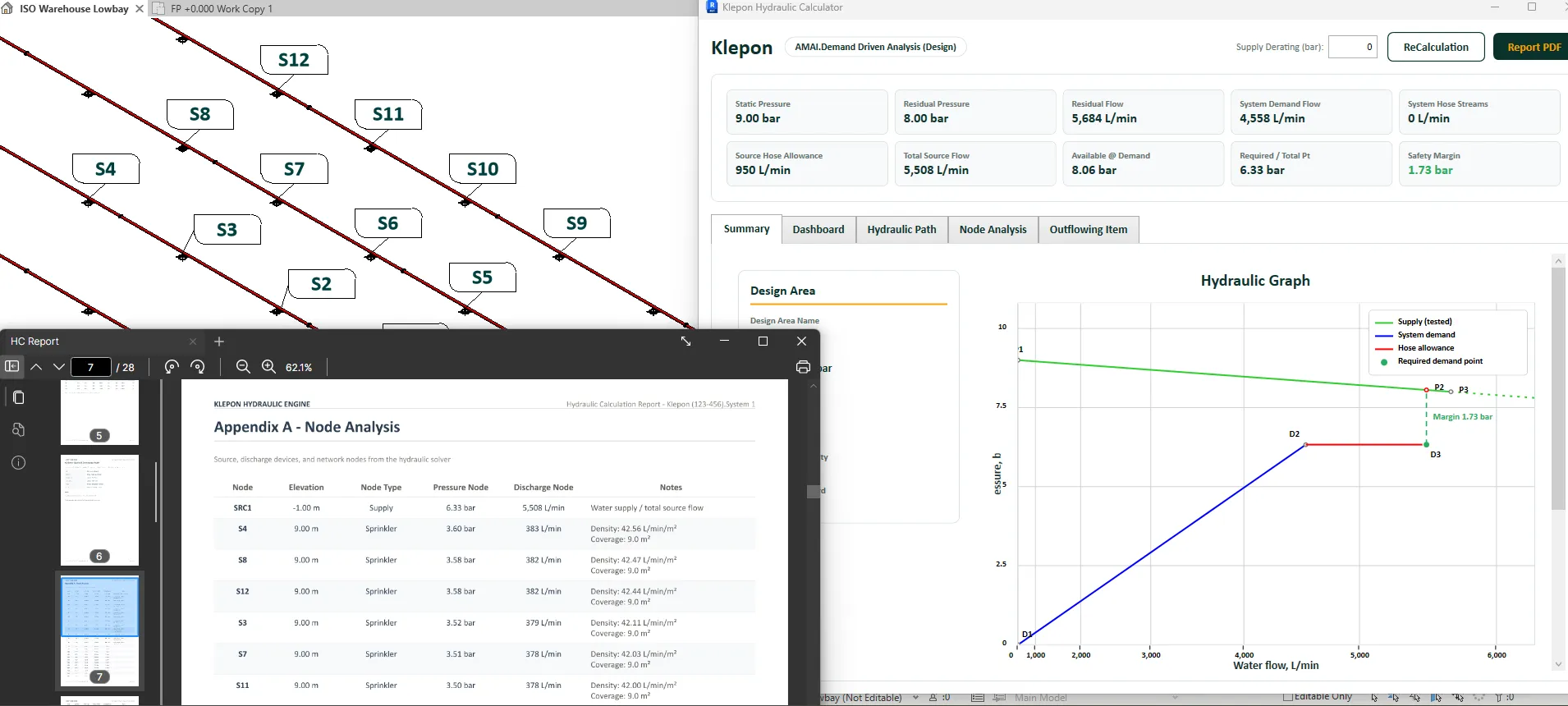
The Revit model becomes the hydraulic model.
One Model. Connected Hydraulic Data.
Hydraulic design is rarely a one-time calculation.
Pipe sizes change. Routing changes. Demand areas move. Coordination changes the system.
With KLEPON, the calculation changes with the design.
This is where a significant amount of engineering time can be saved.
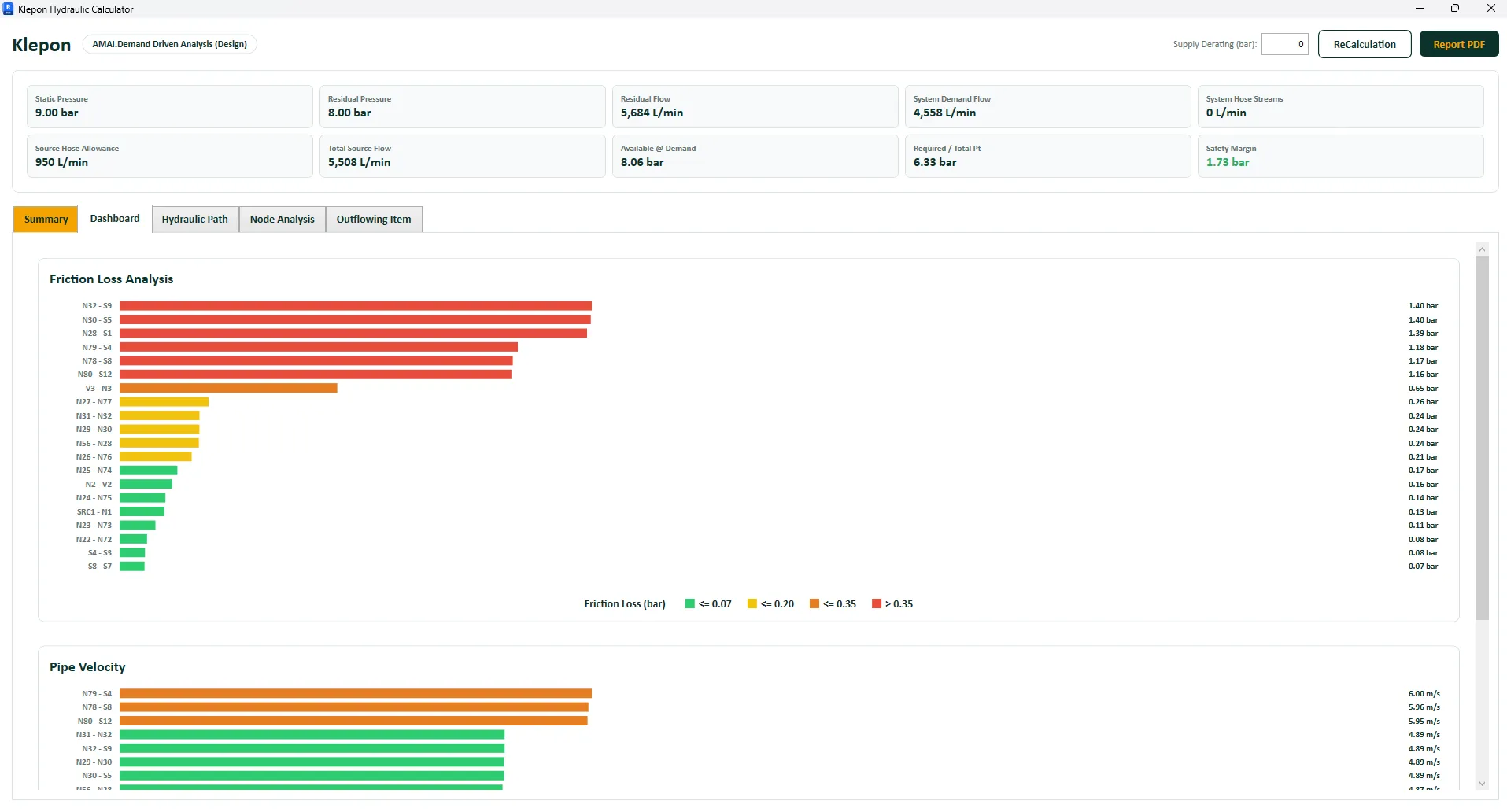
The result:
The calculation changes with the design — saving a significant amount of engineering time.
- 1Model
- 2Calculate
- 3Analyse
- 4Adjust
- 5Recalculate
Understand System Demand at a Glance
The hydraulic dashboard brings the key calculation results together in one place.
Instead of searching through pages of calculation sheets, engineers can quickly review the overall condition of the system, including information such as:
- System Demand Flow
- Calculated system demand
- Hose Allowance / Streams
- Additional flow requirements
- Total Source Flow
- Total demand on the water supply
- Available at Demand
- Available supply pressure at calculated flow
- Required Pressure
- Pressure required by the network
- Safety Margin
- Available pressure minus required pressure
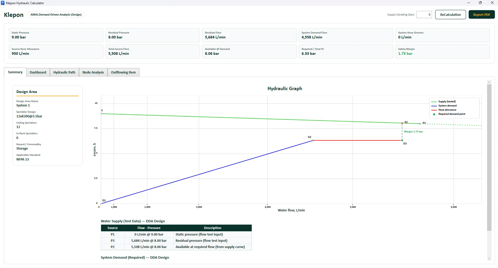
This provides an immediate answer to the most important question:
Does the available water supply satisfy the system — and by how much?
Ready to Build Smarter Fire Protection Workflows?
Let's work together to deliver better projects, faster.